
Pneumatic Actuator Guide 2026: Complete Buyer Manual for Valve Automation
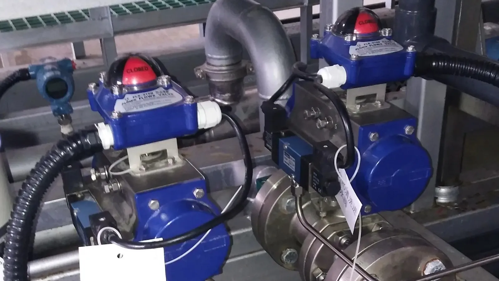
Table of Contents
Most pneumatic actuator searches end in the same place: a valve that needs automating, a stack of supplier quotes, and no reliable way to tell which actuator actually fits. Pneumatic actuators look similar from the outside — a compact body, an air port or two, a flange and a drive — but the mechanism inside, the torque it delivers, and the way it behaves when the air supply fails decide whether a valve opens and closes for a decade or jams in its first season. A standard plant air supply of 5.5 bar drives a product range that spans roughly 8 Nm on a small ball valve up to 200,000 Nm on a pipeline-class scotch yoke unit, so "one size fits all" thinking is the fastest way to overspend or underspec.
This guide walks through what a pneumatic actuator is and how it converts compressed air into rotation, how the three main mechanisms — rack and pinion, scotch yoke and linear — differ in torque profile and price, how to calculate the torque your valve actually needs, what the air supply has to deliver in pressure, flow and quality, how fail-safe logic works in double acting and spring return designs, and which standards (ISO 5211, NAMUR) keep actuator and valve interchangeable across manufacturers. By the end you will be able to read a supplier's torque table, spot an undersized actuator, and send a spec sheet that gets you a usable quote on the first pass.
Keep reading for more!
The Snapshot
- A pneumatic actuator converts compressed air (typically 2–8 bar) into rotary or linear motion to open and close valves; the PNEUMACTUATOR product line covers roughly 8 Nm to 200,000 Nm of output torque.
- Three mechanisms dominate: rack and pinion (constant torque, compact, common up to about 8,000 Nm), scotch yoke (torque that rises toward the stroke ends, from around 1,000 Nm to 200,000 Nm for large valves), and linear cylinders (thrust for globe and gate valves, typically 2–50 kN).
- Size an actuator to the valve's breakaway torque plus a safety factor — commonly 1.25 for double acting and 1.5 for spring return — and re-check the torque at your actual site air pressure, because output scales linearly with supply pressure.
- Fail-safe comes from spring return (single acting) designs: the spring drives the valve to a fail-closed or fail-open position when air pressure drops; double acting actuators hold position and need an accumulator or lock-up valve for fail-safe duty.
- ISO 5211 (F03–F25 flange patterns) and NAMUR (VDI/VDE 3845, 80×30 mm and 30×80 mm accessory patterns) make actuators, valves and accessories from different makers physically interchangeable.
- Standard operating temperature is −20 to +80 °C; low-temperature (−40 °C) and high-temperature (up to roughly 150 °C with special seals) variants are available from most manufacturers.
What Is a Pneumatic Actuator?
A pneumatic actuator is a mechanical device that converts the energy of compressed air into motion. In valve automation — the use case that drives the vast majority of industrial actuator sales — that motion is either a 90-degree rotation (quarter-turn actuators for ball, butterfly and plug valves) or a straight push-pull stroke (linear actuators for globe and gate valves). The actuator bolts onto the valve, its drive engages the valve stem, and a solenoid valve on top sends air into one side of the actuator or the other to turn the valve.
Why pneumatics at all? Three properties keep pneumatic actuators in the specification on most plants. First, speed: a small rack and pinion actuator completes a 90-degree stroke in roughly one to three seconds at 5.5 bar with properly sized ports — fast enough for process isolation and emergency shutdown duties. Second, torque density: a compact actuator a few hundred millimetres long delivers thousands of Newton-metres, which an electric actuator of the same size class cannot match without gearing. Third, inherent safety: with no electrical components inside the actuator body, pneumatic units are widely used in hazardous areas where a spark would be a problem — the electrical parts (solenoid, limit switch) sit outside and are specified separately.
There are trade-offs, of course. A pneumatic actuator is only as reliable as its air supply, so plants running actuators need a compressor, dryers and filtration. Positioning accuracy for throttling duty is weaker than a modern electric or electro-hydraulic positioner, and air consumption is a running cost that does not appear on the purchase order. The pneumatic vs electric decision is covered in more depth in our pneumatic vs electric actuator comparison; this guide assumes you have already chosen pneumatics and now need to specify the actuator correctly.
How Air Pressure Becomes Valve Torque
Every pneumatic actuator, whatever its mechanism, works on the same physics: compressed air pushes a piston, the piston pushes against a gear or yoke, and the gear or yoke rotates the output shaft. The force available from a piston is pressure times area — a 100 mm bore piston supplied at 5.5 bar (0.55 MPa) develops roughly 4.3 kN of force (π × 0.05² m × 550,000 Pa). How much of that force reaches the output shaft as torque depends on the pitch radius of the pinion or the geometry of the yoke, and on internal friction. Manufacturers convert all of this into published torque tables, typically rated at a standard supply pressure of 5.5 or 5.6 bar, with separate figures for air start, air end, and (on spring return models) spring start and spring end.
Torque varies through the stroke — and that matters
A rack and pinion actuator delivers roughly constant torque across the full 90 degrees, because the pinion pitch radius does not change. A scotch yoke is different: the yoke geometry means output torque is lower mid-stroke and rises sharply toward both ends — often 1.5 to 2 times the mid-stroke value at the ends. That profile happens to match valve behaviour, because the highest torque demand on a quarter-turn valve (breakaway torque, the force needed to start the disc or ball moving from rest) occurs at exactly 0 degrees and 90 degrees. This is the single most important concept in actuator sizing, and it is why the same valve can be driven by a smaller scotch yoke than a rack and pinion in large sizes.
Air consumption and speed
Every cycle consumes the swept volume of the piston(s) at supply pressure. A small rack and pinion unit uses on the order of 0.5–2 litres per cycle; a large scotch yoke can use tens of litres. To size a compressor, multiply per-cycle consumption by cycles per minute and add 25–30% margin for leakage and future actuators. Stroke time is set by air pressure, port size and internal volume, and is tuned with adjustable speed control (flow restrictors) on the exhaust ports — plants commonly run cycle times of one to three seconds for small units and five to fifteen seconds for large scotch yokes where the moving mass and valve forces are much bigger.
Three Mechanisms: Rack and Pinion, Scotch Yoke, Linear
Ask a supplier for "a pneumatic actuator" and you will be shown three different machines. They share the same air supply and the same ISO 5211 flange, but their torque profiles, size ranges and price points are different enough that picking the wrong one means either paying for capability you cannot use or jamming a valve.
| Mechanism | Output type | Typical torque / thrust band | Torque profile | Typical valves |
|---|---|---|---|---|
| Rack and pinion | Quarter-turn rotary | ≈ 8 – 8,000 Nm | Roughly constant through stroke | Ball, butterfly, plug (small to medium) |
| Scotch yoke | Quarter-turn rotary | ≈ 1,000 – 200,000 Nm | Rises toward stroke ends | Large ball, plug, butterfly, dampers |
| Linear (cylinder) | Push-pull thrust | ≈ 2 – 50 kN (larger custom) | Constant force, speed varies | Globe, gate, knife gate, slide valves |
Rack and pinion
Two pistons face each other, each carrying a toothed rack; both racks mesh with a central pinion on the output shaft. Air pushes both pistons outward, the racks turn the pinion, and the shaft rotates 90 degrees. The design is compact, inexpensive in small sizes, and delivers predictable, roughly constant torque — which is why it dominates the market below a few thousand Newton-metres. It is the default choice for ball and butterfly valves up to DN300 or so in standard service. The PNEUMACTUATOR rack and pinion line, with both double acting and spring return versions, covers the bulk of this range with ISO 5211 F03–F16 flanges.
Scotch yoke
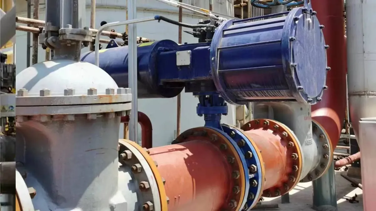
A single piston rod drives a sliding yoke; a pin on the output crank rides in the yoke slot, converting linear motion into rotation. Because the lever arm between the crank pin and the output centre changes through the stroke, torque is low mid-stroke and high at the ends — exactly where a big ball or plug valve needs maximum breakaway force. Scotch yoke actuators take over where rack and pinion units stop being economical, typically from about 1,000 Nm upward, and they are the standard for pipeline valves, large plug valves and any quarter-turn duty above roughly 20,000 Nm. They are longer and heavier than rack and pinion units of similar torque, and their torque curve must be checked against the valve's torque curve rather than compared by a single rated number. See our dedicated scotch yoke range and the rack and pinion vs scotch yoke comparison for the full trade-off.
Linear actuators
Where the valve stem moves straight, a rotary actuator is the wrong tool. Pneumatic linear actuators — cylinders with a piston rod — provide thrust directly to globe, gate and knife gate valves, typically rated in kilonewtons rather than Newton-metres. A 50 mm bore cylinder at 5.5 bar delivers about 1.1 kN; a 200 mm bore cylinder delivers roughly 17 kN. Linear units dominate control-valve applications when paired with a positioner, and they are the simplest, least expensive way to automate a rising-stem valve. The PNEUMACTUATOR linear actuator range covers common industrial bores with the same accessory interfaces as the rotary line.
Torque Calculation: Sizing the Actuator to the Valve
An actuator that is too small stalls against the valve and burns air while the process runs unprotected; one that is too large costs money, cycles slowly and can over-stress the valve stem. Sizing is a four-step calculation, and the full worked method lives in our step-by-step torque calculation guide — here is the version you need to check a quote.
Step 1: Get the valve's torque requirement
The valve manufacturer's data sheet lists breakaway torque (to start motion), running torque (to keep moving) and reseat torque (to close). Breakaway is typically the largest and is the number that sizes the actuator. It is not a fixed value: it grows with line pressure, differential pressure across the valve, temperature, media and how long the valve has sat closed — a ball valve that has been closed for a month can need substantially more torque than the fresh-off-the-bench figure.
Step 2: Apply a safety factor
Industry practice is to multiply breakaway torque by a safety factor: commonly 1.25 for double acting actuators and 1.5 for spring return, the higher figure for spring return because the spring end must overcome the same valve with less available torque. Some operators use 1.5 for critical or unproven services. Example: a DN150 butterfly valve with 120 Nm breakaway at operating conditions needs a double acting actuator rated at least 120 × 1.25 = 150 Nm, or a spring return unit rated at 120 × 1.5 = 180 Nm at the spring end.
Step 3: Correct for your site air pressure
Catalogs rate torque at 5.5 or 5.6 bar. Output torque scales linearly with supply pressure, so an actuator rated 150 Nm at 5.5 bar delivers about 150 × (4.0 ÷ 5.5) ≈ 109 Nm on a plant running 4 bar — below the 150 Nm requirement. Compare actuator torque at the minimum pressure you will actually supply, not the catalog pressure, and remember the pressure drops when other consumers draw air at the same time.
Step 4: Check both directions on spring return
A spring return actuator has four published figures: air start, air end, spring start, spring end. The valve must be driven by the spring end torque in the fail direction and by the air end torque in the powered direction — both must clear the valve requirement with the safety factor applied. As a rule of thumb, spring end torque lands around 70% of the air end torque for the same actuator size, which is why spring return units are typically one size class larger than double acting for the same valve.
Air Supply: Pressure, Flow and Quality
Actuators are sold as standalone products, but they run on a utility — the plant compressed air system — and the quality of that utility decides how long the actuator lasts. Three parameters matter: pressure, flow and air quality.
Pressure
The standard operating band is 2–8 bar. Below about 2 bar most actuators lack the force to move their own internals, let alone a valve; above 8 bar you exceed the rating of standard components and seals. The common design point is 5.5–6 bar, and a pressure regulator at each actuator (or at least per zone) is standard practice so that torque stays predictable when the main line fluctuates. A filter-regulator-lubricator (FRL) unit mounted ahead of the solenoid is the standard package on plant installations.
Flow
Flow decides cycle speed. The relevant number is the actuator's air consumption per cycle multiplied by the cycle rate. A medium rack and pinion unit consuming about 4 litres per cycle at 5.5 bar, cycled 10 times per minute, draws roughly 40 litres per minute of free air — and the compressor must serve every actuator plus leak losses, so sizing the compressor with 25–30% headroom is common practice. Undersized supply lines or undersized solenoid ports are the usual reasons a "slow" actuator turns out to be a flow problem, not an actuator problem.
Quality
Compressed air carries water, oil and particles, and all three shorten actuator life. The common specification for general plant air is ISO 8573-1 class 4.4.3 or better: particles filtered to 15 µm, pressure dew point below +3 °C, oil content below 1 mg/m³. For actuators running outdoors in cold climates, a lower dew point matters because condensed water freezes inside the body and jams the mechanism — the −20 °C lower limit of a standard actuator assumes reasonably dry air. Many modern actuators are pre-lubricated and designed to run dry; if the manufacturer says no lubrication is required, do not add oil, because over-lubrication attracts dust and can soften seals.
Fail-Safe Logic: Double Acting vs Spring Return
When the air supply fails — compressor trip, blocked line, a ruptured hose — every pneumatic actuator does something. The question is whether that something is controlled. This is the fail-safe decision, and it is usually the first specification a process engineer writes down, before torque.
Double acting: air in both directions, no inherent fail position
A double acting actuator uses air to open and air to close. Lose the air and the valve stays wherever it was — which might be fine for a throttling valve on a non-critical loop, and dangerous for a fuel shut-off. If fail-safe is required on a double acting installation, you add hardware: a lock-up valve that traps air in the actuator to hold position, or an accumulator / reserve air tank sized for enough cycles to complete the required action, or a separate spring-return actuator on the critical valve. Each adds cost and complexity, which is why fail-safe duty usually starts with the next option.
Spring return: the spring is the fail-safe
A spring return (single acting) actuator has springs on one side of the piston. Air compresses the springs and drives the valve one way; losing air lets the springs drive it back. The fail position is set by how the springs are installed: spring-to-close (fail closed, FC) for media that must be isolated on air loss — fuel, steam, toxic or flammable fluids — and spring-to-open (fail open, FO) for services that must keep flowing, such as cooling water or purge air. The same actuator can be converted by changing the spring arrangement, which is why suppliers quote "FC" and "FO" as separate configurations of the same hardware.
Spring torque is the number that matters
The spring end torque, not the air end, is what guarantees the fail action, and it must clear the valve's breakaway torque at the worst case — a closed valve that has been seated for weeks, at minimum line temperature. Because spring torque runs roughly 70% of air torque in the same housing, spring return actuators are commonly specified one size up from the double acting equivalent. Two related guides go deeper here: double acting vs spring return for the decision framework and spring return working principle for the air-stroke-to-spring-stroke mechanics.
ISO 5211 and NAMUR: Standards That Keep Parts Interchangeable
Two standards do most of the work in making the actuator market interchangeable: ISO 5211 for the actuator-to-valve interface and NAMUR (VDI/VDE 3845) for the accessory-to-actuator interface. If you are buying from a manufacturer, these two standards are what let you bolt a valve from one maker onto an actuator from another without custom machining.
ISO 5211: the flange and drive
ISO 5211 defines the mounting flange dimensions between actuator and valve — the bolt circle, bolt size and number of bolts — plus the drive coupling (commonly a female square or keyed drive that engages the valve stem). Common flange sizes are F03, F04, F05, F07, F10, F12, F14, F16 and F25, with bolt circle diameters from 36 mm (F03) up to 254 mm (F25). Matching a valve's flange and stem size to the actuator's is the mechanical heart of the "will it fit" question, and it is why a spec sheet should state the ISO 5211 flange and drive size, not just the torque. Our ISO 5211 mounting guide lists the full pattern table.
NAMUR: the accessory interface on top
NAMUR, standardized as VDI/VDE 3845, defines the mounting pattern on top of the actuator for solenoids and limit switch boxes — the familiar 80×30 mm and 30×80 mm hole patterns with the shaft visible through the centre. A NAMUR solenoid bolts directly onto the actuator top without brackets, and a NAMUR limit switch box mounts the same way, which is why the same solenoid and the same switch box fit actuators from dozens of manufacturers. The standard also covers the drive shaft dimensions and the 4 mm pilot holes used for accessory alignment.
Why this matters for buyers
Interchangeability changes the buying math. If your plant standardizes on ISO 5211 and NAMUR, you can source actuators and valves from different suppliers, keep one spare accessory set for every actuator in the facility, and switch brands on the next order without touching the piping. That is also the argument for buying from a manufacturer that publishes flange and NAMUR compliance openly rather than selling "compatible with" marketing language.
Accessories: Solenoids, Limit Switches, Positioners
An actuator alone is just a motor with no controls. The accessories decide how it is commanded, how its position is reported, and how it behaves in an emergency. The full accessory landscape is covered in our actuator accessories guide; the short version is five components.
- NAMUR solenoid valve: the control element that sends air to the open or close port. Most are 5/2 or 3/2 way, 24 V DC (or 110–230 V AC), rated for the 2–8 bar supply band, with a manual override for commissioning. Choose the coil voltage to match the plant control system; 24 V DC is the default in most modern plants.
- Limit switch box: reports valve position electrically. Typically 2–4 mechanical SPDT switches or inductive proximity sensors, mounted to the NAMUR pattern, with visual position indication. For hazardous areas, the switch box is the component that needs an Ex rating, not the actuator.
- Positioner: for proportional (throttling) control. It takes a 4–20 mA or 0–10 V signal, compares it to actual shaft position, and modulates the air to hold the valve at the commanded opening. Adds accuracy at the cost of air consumption — a positioner-equipped actuator can use noticeably more air than an on-off unit.
- Filter-regulator (FR or FRL): conditions the air right at the actuator — filters to protect the solenoid, regulates pressure to stabilize torque, and optionally lubricates. On most plants this is mandatory, not optional.
- Manual override and speed controls: a handwheel or lever to operate the valve when air is down, and adjustable flow restrictors to set opening and closing speeds independently — especially important on large valves where slamming shut at full speed can damage the disc or cause water hammer.
Operating Environment: Temperature, Corrosion, Hazardous Areas
An actuator that fits the valve can still fail on the site if the environment exceeds its rating. Three environmental questions belong on every specification.
Temperature
Standard actuators are rated for −20 to +80 °C ambient, which covers indoor plants and most temperate outdoor duty. Outside that band, options exist: low-temperature versions with special seals and low-temperature greases are commonly rated to −40 °C for arctic and refrigerated service, and high-temperature versions with FKM or PTFE seals extend the top end to roughly 150 °C for steam-adjacent duty. Two cautions: cold affects the fail-safe springs (spring torque is rated at ambient temperature), and hot installations need the actuator sized with the air at operating temperature, because hot air at the same gauge pressure carries less force per stroke when the system is designed around cold start conditions.
Corrosion
Standard bodies are anodized aluminium with an epoxy paint finish, adequate for indoor and dry outdoor duty. Coastal, offshore, chemical and wastewater sites step up to higher protection: stainless steel bodies (commonly 316L), electroless nickel plating on the pistons and shafts, and heavier epoxy systems. Manufacturers typically publish salt spray ratings on the order of 500–1,000 hours for epoxy-finished bodies — useful as a comparison number, less useful as a lifetime-warranty claim, so for marine duty ask for the stainless option directly. Enclosures for switch boxes and solenoids are usually rated IP67 as standard, with IP68 available for washdown and submersion duty.
Hazardous areas
Pneumatic actuators are popular in hazardous areas precisely because the actuator itself is non-electrical — the body, springs and air are inherently spark-free. The electrical accessories are a different story: a solenoid coil or limit switch in an Ex zone must carry an appropriate certification (ATEX, IECEx or regional equivalent) matched to the zone — gas zones 1 and 2, dust zones 21 and 22 — and the temperature class. A frequent beginner mistake is buying an "ATEX actuator" when what was actually needed was an ATEX solenoid and switch box on a standard actuator. Our ATEX pneumatic actuator guide walks through zone classification and certification wording.
Selection by Valve Type: Ball, Butterfly, Plug and Linear
The valve type drives the actuator choice more than any other single factor, because each valve family has a characteristic torque profile and motion. The table below is a starting point — treat the figures as typical order-of-magnitude anchors, not substitutes for the valve data sheet.
| Valve type | Motion | Typical mechanism | Typical size / torque anchor | Notes |
|---|---|---|---|---|
| Ball valve (floating) | Quarter-turn | Rack and pinion | DN15–DN150, 8–2,000 Nm | High breakaway after long closed periods; check seat material friction |
| Ball valve (trunnion) | Quarter-turn | Scotch yoke | DN150+, 2,000–200,000 Nm | Pipeline service; torque grows steeply with pressure class |
| Butterfly valve | Quarter-turn | Rack and pinion; scotch yoke for large sizes | DN50–DN600, 30–8,000 Nm | Lowest torque per size — the economical automation choice for big lines |
| Plug valve | Quarter-turn | Scotch yoke | DN50–DN400, 500–50,000 Nm | High breakaway from plug-to-body friction |
| Globe / gate valve | Linear | Linear cylinder | 2–50 kN thrust | Rising stem; thrust, not torque, is the sizing unit |
Butterfly valves: the volume play
Butterfly valves have the most favourable torque-to-size ratio of the quarter-turn family, so they are the standard automation target in water, HVAC, chemical and process duty. A DN150 butterfly valve in soft-seated design typically needs a few hundred Newton-metres at breakaway, which lands comfortably inside the rack and pinion range; moving to DN600 and above, or to metal-seated high-pressure designs, pushes the requirement up into scotch yoke territory. Our butterfly valve actuator selection guide goes size by size.
Ball valves: torque grows with pressure class
Floating ball valves in small sizes automate well with compact rack and pinion units; trunnion-mounted ball valves in pipelines and high-pressure service need the end-of-stroke torque of a scotch yoke. The same nominal size at PN16 versus PN160 can have very different breakaway figures, so size from the pressure-class-specific torque data. See ball valve actuator sizing for the worked examples.
Buyer Checklist: What to Send a Supplier
A good actuator quote starts with a good enquiry. Suppliers (including ours, from the factory in Wenzhou, China) can quote faster and more accurately when the enquiry carries the information below. Missing torque data is the single most common reason quotes come back wrong.
- Valve identity: make, model, type (ball / butterfly / plug / linear), nominal size and pressure class (e.g. DN150 PN16).
- Torque requirement: breakaway, running and reseat torque at operating conditions, or the valve data sheet — plus the line pressure, differential pressure and media.
- Duty: on-off or throttling, cycle frequency (cycles/hour), and any emergency shutdown role.
- Fail-safe: fail closed, fail open, or hold position; double acting or spring return preference.
- Air supply: available pressure range (e.g. 4–6 bar), and whether an FRL is included.
- Speed: required opening/closing time, if specified by the process.
- Environment: ambient temperature range, indoor/outdoor, coastal or corrosive atmosphere, hazardous area zone and certification needed.
- Accessories: solenoid (voltage), limit switch box (contacts, Ex rating), positioner (signal type), manual override.
- Standards: ISO 5211 flange size if you know it, plus any project standards (ISO 9001 quality system, pressure equipment directives, paint specs).
- Commercial: quantity, target lead time, packaging for export, and whether OEM/private-label branding is required.
Sending all ten items takes five minutes and removes an entire round of clarification emails. When in doubt, send the valve data sheet and the operating conditions — sizing engineers would rather have too much than too little.
Questions Buyers Ask
1. How do I know which actuator size my valve needs?
From the valve manufacturer's torque data: breakaway torque at operating conditions, times a safety factor of 1.25 (double acting) or 1.5 (spring return), checked against the actuator's rated torque at your actual supply pressure. If the valve data sheet is not available, send the valve make, model and size to the supplier — most actuator manufacturers, including PNEUMACTUATOR, maintain valve torque reference tables and will size the unit for you.
2. Double acting or spring return?
If the process requires a defined valve position when air fails, spring return. If hold-position is acceptable or the valve is non-critical, double acting is smaller and cheaper for the same torque. The fail-safe decision should come from the process engineer, not the actuator supplier.
3. Why is the actuator's torque at my plant lower than the catalog?
Because output scales linearly with supply pressure. A unit rated 200 Nm at 5.5 bar delivers roughly 145 Nm at 4 bar (4 ÷ 5.5 × 200). Compare torque at your minimum supply pressure, not the catalog pressure.
4. Do pneumatic actuators need lubricated air?
Many modern actuators are pre-lubricated and designed to run dry, and manufacturers increasingly recommend non-lubricated operation to avoid oil attracting dust and degrading seals. Check the datasheet; if it says no lubrication required, fit a filter-regulator without the lubricator.
5. Can I use one actuator brand with another brand's valve and accessories?
With ISO 5211 flanges and NAMUR accessory patterns, yes in physical terms — the bolt patterns and drive sizes are standardized. Electrically and pneumatically, check the compatibility of voltages, ports and signal types. That interchangeability is exactly why these standards exist.
6. How much does a pneumatic actuator cost?
Roughly, a small rack and pinion double acting unit (under 100 Nm) runs in the tens of US dollars factory-direct at volume; a 10,000+ Nm scotch yoke runs into the thousands. Spring return adds roughly 15–30% over double acting at the same size, and accessories typically add 20–50% to the actuator price. Factory-direct pricing from manufacturers like PNEUMACTUATOR generally undercuts distributor retail by a wide margin at container quantities, which is why most importers buy direct.
The Bottom Line
A pneumatic actuator is a simple machine with an unforgiving spec sheet: get the mechanism, the torque and the fail-safe logic right and it will cycle for hundreds of thousands of operations; get any one wrong and the valve either stalls, slams, or sits in the wrong position during an upset. The whole selection process compresses into five checks — mechanism matches the valve family, breakaway torque plus safety factor clears at your minimum air pressure, fail-safe position matches the process requirement, ISO 5211 flange and drive match the valve, and the environment (temperature, corrosion, Ex zone) is inside the rating. Air quality deserves the same respect as the actuator itself, because dry, filtered air at a regulated 5.5–6 bar is what makes the rest of the plan work.
When you are ready to spec, send us the checklist from this guide — valve model, size, torque, fail position, air pressure and environment — and our engineers will size the actuator, confirm the ISO 5211 flange and accessories, and return pricing with lead time. Reach us at the contact page or email sales@pneumactuator.com — we respond within 24 hours on business days.
Next Step
Ready to Spec Your Valve Actuator Package?
Send us your valve type, torque requirement and air supply — our engineers respond within 24 hours with sizing and pricing.
Written by
Ray ChanActuator engineer & technical writer. Ray helps global importers and integrators source factory-direct pneumatic actuators and valve automation packages.