
Spring Return Actuator Working Principle: How Fail-Safe Works
Table of Contents
A compressor trips at 2 a.m., or a solenoid loses its pilot signal, and the valve in the line has a few seconds to decide what it will do. If that valve feeds fuel to a burner, protects a pressure vessel, or supplies water to a cooling circuit, "stay where it was" is not a workable answer. The spring return pneumatic actuator is the component that makes the decision without waiting for an operator, a PLC, or even electricity: the moment air pressure falls below the spring force, a set of compressed springs rotates the valve to its fail position — closed or open, whichever the process requires.
Also called a single acting actuator, the spring return design is one of the most widely specified fail-safe mechanisms in valve automation. This guide breaks down the working principle in plain engineering terms: the two strokes (air stroke and spring stroke), where the torque actually comes from, how spring sets and pre-load work, how to read a spring return torque curve, how FC and FO fail positions are chosen, and how a spring set is selected for a specific valve.
The Snapshot
- A spring return (single acting) actuator uses air for one stroke and compressed springs for the return stroke — the return is automatic on air loss, and the return stroke itself needs no electrical power.
- Every model publishes four torque values: air stroke start/end and spring stroke start/end. The two END values are usually the sizing-critical ones, because the actuator is weakest at the ends of each stroke.
- SR-series rack and pinion spring return actuators cover 8 – 1000+ Nm air stroke torque on a 3 – 8 bar supply, rotating 90° with adjustable ±5° travel stops.
- Spring cartridges hold 4 – 12 springs per side with adjustable pre-load, so seating torque can be tuned after installation without replacing parts.
- Fail position is specified as FC (spring-to-close) or FO (spring-to-open). As a rough balance guide, a spring set of about one spring per side per bar of supply pressure gives an even torque output across the stroke.
- Size on the weakest point: the minimum of the four torque values — in practice the air end and spring end — must exceed the valve requirement with a safety factor; 25 – 30% is a common starting point.
What Is a Spring Return Actuator?
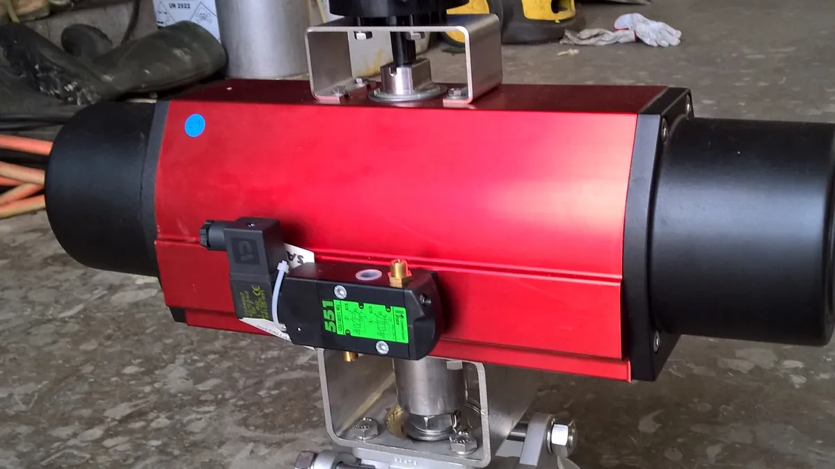
A spring return pneumatic actuator is a valve actuator that performs one stroke with compressed air and the other stroke with mechanical springs. On a quarter-turn design, air moves the output shaft through 90° in one direction; when the air pressure drops or is vented, the springs drive the shaft back through the same 90° in the opposite direction. That second stroke is the fail-safe: it happens by stored mechanical energy alone, with no signal, no motor and no operator in the loop.
The design is built on the same twin-piston rack and pinion base as a standard double acting actuator — hard-anodized aluminum bodies (EN AC-44300), ISO 5211 top and bottom mounting interfaces, and a NAMUR VDI/VDE 3845 pad for the solenoid valve. The spring return version adds a spring cartridge that pushes the pistons back when air pressure falls. The PNEUMACTUATOR SR series covers air stroke torque from 8 to over 1000 Nm on a 3 – 8 bar supply, in both spring-to-close and spring-to-open configurations, with ATEX options for hazardous areas.
Because the spring cartridge is a modular insert, the same actuator body can be assembled as double acting or spring return — you add or remove springs rather than buying different hardware. That matters for distributors who want to stock one body type and configure it per order. If you are comparing the two architectures in detail, our guide on double acting vs spring return actuators covers the fail-safe logic and trade-offs side by side.
Air Stroke vs Spring Stroke: Two Torque Sources
Think of a spring return actuator as two engines sharing one gearbox. On the air stroke, compressed air enters through the NAMUR solenoid pad, presses on both pistons, and the rack rotates the pinion and output shaft. Torque comes from the air: supply pressure times piston area times the effective lever arm of the mechanism. Along the way, the pistons compress the springs, storing mechanical energy for the return trip.
On the spring stroke, the air has gone — either the supply failed or the solenoid vented it. The springs extend, push the pistons back, and rotate the shaft in reverse. Torque comes from the springs: spring rate times deflection times the same lever arm. Nothing in that path needs electricity, which is why spring return actuators are a natural fit for safety-instrumented systems and for ATEX-classified zones where powering a motor back to position is either slow or undesirable.
Each stroke has two meaningful torque values. At the start of the air stroke the springs are barely compressed, so the air torque is at its highest; as the stroke progresses and spring compression builds, the available air torque falls to its minimum at the end. The spring stroke behaves in mirror image: torque is highest at the start (springs fully compressed) and falls as the springs extend toward the fail position. Manufacturers publish all four values — air start, air end, spring start, spring end — and sizing an actuator without checking each one against the valve's own torque requirement is where most undersizing errors start.
How the Fail-Safe Cycle Works, Step by Step
- At rest — springs hold the valve. With no air applied, the spring cartridge keeps the pistons at the fail position and maintains the pre-load that seats the valve. This is the position the valve stays in during a shutdown, day after day.
- Air is applied. The solenoid shifts, and supply air (typically regulated to 3 – 8 bar) pressurizes both pistons. The pistons move inward, the rack rotates the pinion, and the springs begin to compress.
- Mid-stroke — torque trades off. Air torque is at its maximum near the start and falls as spring compression grows. The stroke speed is governed by how fast air fills the chamber and how fast the exhaust is throttled, which is why flow control valves on the ports are the usual way to tune opening and closing times.
- End of air stroke — valve in operating position. The output shaft has rotated 90° and the springs are fully compressed. Adjustable travel stops (±5° on the AT/SR mechanism) limit rotation precisely so the valve seats in the right place. Air pressure holds this position for as long as the process needs it.
- Air is lost. Supply pressure drops below the force the springs exert, or the solenoid vents the chamber. The springs take over — no signal, no electricity, no waiting.
- Return and seat. The springs drive the pistons back and rotate the valve to the fail position. The spring end torque seats the valve, and the cycle ends where it started.
The fail-safe stroke is not an emergency feature that sits idle — it is exercised every time the plant shuts down, every time the system is depressurized for maintenance, and on every ESD test. That is why spring return actuators are rated for high cycle counts and why the rack and pinion mechanism behind the SR series is 1,000,000-cycle tested.
Spring Sets and Pre-Load
The spring cartridge is a set of coil springs arranged around the piston assembly — on the SR series, 4 – 12 springs per side depending on frame size and torque requirement. The cartridge is a maintenance-free, field-serviceable unit: you can remove or add springs as a complete assembly rather than wrestling individual coils, and the same cartridge system is what lets a double acting body convert to spring return.
Pre-load is the compression the springs carry when the actuator is at rest in the fail position. It is a deliberate setting, not an accident of assembly: it defines the seating torque the valve receives at the fail position, and it defines how much air pressure is needed just to begin the air stroke. Because pre-load is adjustable on the SR series, you can fine-tune seating torque on site — after the valve is installed and measured — without replacing any parts.
Two consequences follow from the spring set being part of the air stroke's load. First, a spring return actuator for a given valve is usually one or two frame sizes larger than the double acting equivalent, because the air must overcome the spring force in addition to moving the valve. Second, the spring count and the supply pressure can be traded against each other: a balanced configuration of about one spring per side per bar of supply pressure (for example, 4 springs per side at 4 bar) produces an even torque profile, while an unbalanced pairing (for example, 6 springs per side at 5.5 bar) shifts torque toward one end of the stroke — useful when the valve's own torque curve is asymmetric, as it often is for ball valves with high breakaway torque at the closed position.
Reading the Torque Curve: Start and End Values
The four torque values are not interchangeable — each one guards a different moment in the cycle. The table below shows what each value has to beat.
| Torque value | Where it applies | Why it matters |
|---|---|---|
| Air stroke start | Start of air stroke (fail position) | Highest air torque point; must break the valve out of the fail position and get the stroke moving |
| Air stroke end | End of air stroke (operating position) | Lowest air torque point; must hold and move the valve with springs fully compressed |
| Spring stroke start | Start of spring stroke (operating position) | Highest spring torque; must break the valve out of the operating position the instant air is lost |
| Spring stroke end | End of spring stroke (fail position) | Lowest spring torque; must seat the valve in the fail position — often the design-critical figure |
The sizing logic follows from the table: the minimum of the four values is the torque the actuator can actually deliver at its weakest moment, and that weakest value must still exceed the valve requirement at the corresponding position. In practice the two end values — air end and spring end — are the ones that decide the frame size, which is why manufacturers' spring return torque tables list start and end torques rather than a single number. When the end-of-stroke torques come out nearly equal, the selection is close to optimal: the air stroke and the spring stroke are balanced against each other.
One more property is worth remembering: air torque scales with supply pressure, spring torque does not. If the plant air header runs at 6 bar today and 4.5 bar after a compressor change, the air stroke values shrink accordingly while the spring values stay fixed. Sizing against the lowest supply pressure you can actually guarantee is the safe habit — the full method is covered in our step-by-step actuator torque calculation guide.
Fail-Safe Position: FC vs FO
Fail-safe position is a process decision before it is a hardware decision. The spring set can be arranged so that the actuator's fail position is closed — spring-to-close (FC) — or open — spring-to-open (FO). Nothing else about the mechanism changes; the springs simply push the valve to the end the process needs.
FC (fail closed) is specified where an open valve on air loss is dangerous: fuel supply lines, chemical dosing, gas regulators, steam systems and emergency shutdown valves. If the valve stays open, product keeps flowing into a line that may be depressurized, overheated or under maintenance. Closing it starves the incident.
FO (fail open) is specified where a closed valve on air loss is the greater hazard: cooling water circuits, ventilation dampers and purge air lines. Here the risk runs the other way — stopping the cooling flow or sealing off the ventilation is worse than letting it continue. FO keeps the medium moving so the process stays within its safe envelope.
The choice comes down to one question: with air gone and nobody in the loop, which valve position protects people and equipment? If the answer is not obvious for your line, our engineers work through the process conditions with you before quoting — and for hazardous areas, ATEX-configured spring return versions are available so the fail-safe behaviour and the zone rating come from the same unit.
How Spring Sets Are Selected for a Valve
- Establish the valve torque requirement. You need the breakaway (breakout) torque in both directions, the running torque through the stroke, and the seating torque at both end positions — from the valve manufacturer's data or from measurement.
- Apply a safety factor. Multiply the measured requirement by a factor that covers media, temperature, packing friction and cycle frequency; 25 – 30% is a common starting point in actuator selection practice.
- Pick the frame size on the air end. Choose an actuator whose air stroke END torque, at the lowest supply pressure you can guarantee, exceeds the factored requirement at the operating position. The air stroke start value will be higher, so the end value is the constraint.
- Pick the spring set on the spring end. Within that frame, choose a spring configuration whose spring stroke END torque exceeds the factored requirement at the fail position — the seating condition. This is the step that determines how many springs per side you order.
- Balance springs against pressure. Check the four values together, and confirm the spring count and supply pressure sit in a workable pairing (roughly one spring per side per bar for a balanced profile). If the valve torque is asymmetric, an unbalanced pairing can deliberately bias torque where it is needed.
- Fine-tune on commissioning. Because pre-load is adjustable, the final seating torque can be set against the real installed valve rather than the catalogue value.
Worked examples of this sequence, including how valve torque figures are obtained and factored, are in our actuator torque calculation guide. If you send us the valve model and operating conditions, we run the same selection and recommend an SR-series configuration — including the spring set — with the reasoning attached.
Where Spring Return Actuators Earn Their Keep
Spring return actuators show up wherever a process must be able to fail safely on its own. Typical duty includes emergency shutdown valves on fuel and process lines, safety valves and fire protection systems, gas regulators, ventilation dampers, process lines, storage tanks and steam systems.
In each case the common thread is the same: the consequence of doing nothing on air loss is worse than the consequence of the fail position. A fire protection deluge valve should close (or open, per the system design) the instant air is lost; a cooling water valve should stay open so the exchanger keeps its duty; a tank blanketing regulator should isolate so pressure cannot climb. Because the return stroke consumes no electricity and no signal, the actuator is a dependable final element for safety-instrumented systems — a simple mechanical energy store doing exactly one job, every time. If your site is in a classified area, the ATEX option keeps the same fail-safe behaviour in the zone without adding electrical complexity at the valve.
The Bottom Line
Fail-safe valve automation comes down to a few seconds and one mechanical decision: when the air disappears, the spring set moves the valve where the process needs it — no power, no signal, no delay. Getting that decision right means reading the four torque values, sizing on the weakest end of each stroke, and setting the spring set and pre-load for your actual valve.
Send us your valve model and fail-safe requirement for a spring return actuator recommendation with the spring set sized and quoted within 24 hours.
Next Step
Ready to Spec Your Valve Actuator Package?
Send us your valve type, torque requirement and air supply — our engineers respond within 24 hours with sizing and pricing.
Written by
Ray ChanActuator engineer & technical writer. Ray helps global importers and integrators source factory-direct pneumatic actuators and valve automation packages.