
Pneumatic Actuator vs Electric Actuator: Which Drives Your Valve?
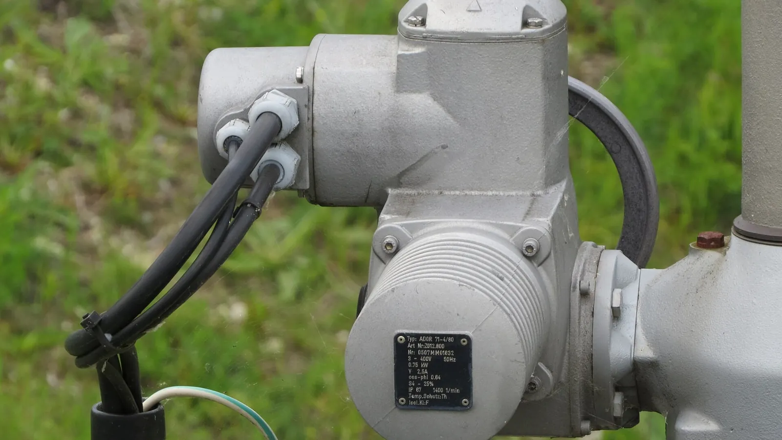
Table of Contents
The actuator bolted to a valve is one of the least glamorous and most consequential components on a process line. It converts a control signal into torque, and the pneumatic vs electric decision behind it quietly shapes operating cost, safety compliance and uptime for years. Choose the wrong drive and you either pay for compressed-air infrastructure a small valve never needed, or watch an electric unit struggle on a duty cycle its motor was never rated for. Both technologies are mature; both fail when they are matched to the wrong service.
This guide compares them on the seven axes that actually decide an order: cycle speed, torque density, explosion safety, installed cost, control precision, maintenance and fail-safe behavior. You will get concrete numbers where they exist, an honest note where the answer depends on your site, and a decision table you can take into a design review. No winner is declared at the end — the right answer is a function of duty cycle, air availability and process risk.
Keep reading for more!
The Snapshot
- Cycle speed: pneumatic quarter-turn actuators typically complete a 90° stroke in 1–5 seconds (our DA-series spec) and speed is tuned with simple flow control valves. Electric units commonly need several seconds to tens of seconds as torque and gear reduction rise.
- Torque range: pneumatic rack-and-pinion actuators cover roughly 8–4,000+ Nm in compact aluminum frames, and scotch-yoke designs extend to 200,000+ Nm; electric quarter-turn units exist at high torque but the motor-and-gearbox package grows quickly.
- Explosion safety: a pneumatic actuator is non-electrical at the valve — no ignition source — which simplifies ATEX compliance; an electric unit in the same zone needs an explosion-proof motor, enclosure and certified wiring.
- Control precision: electric actuators typically position within ±0.1–0.5% of span; pneumatic with a positioner typically holds ±1–2%, which covers most throttling loops.
- Fail-safe: spring-return pneumatic actuators drive the valve to a defined FC/FO position on air loss with no external energy; electric actuators need a battery pack or spring module to do the same.
- Maintenance reality: neither is zero-maintenance — pneumatic wears seals and depends on air quality; electric wears gears, batteries and electronics.
Head-to-Head Comparison
The table below is the version to keep on your desk. Ranges are typical published figures, not worst-case marketing numbers.
| Factor | Pneumatic Actuator | Electric Actuator |
|---|---|---|
| Energy source | Compressed air, 2–8 bar typical (29–116 psi) | Electric motor, 24 VDC / 110–230 VAC typical |
| Cycle speed (90° stroke) | 1–5 s typical, adjustable via flow controls | Several seconds to tens of seconds; faster on small low-torque units |
| Torque range | ~8–200,000+ Nm across rack-and-pinion, scotch yoke and linear designs | Small sizes to tens of thousands of Nm; package grows with torque |
| Explosion safety | Non-electrical at the valve; no spark source; simplifies zone compliance | Requires explosion-proof (Ex d) enclosures, certified motors and cable glands |
| Positioning accuracy | ±1–2% of span with a pneumatic positioner | ±0.1–0.5% of span typical, excellent repeatability |
| Fail-safe on power loss | Automatic with spring return (FC/FO); no energy required | Needs battery backup or mechanical spring module |
| Duty cycle | Continuous cycling without derating (double acting) | Motors commonly rated intermittent (S2/S3, often 25–50%); frequent cycling needs a larger frame |
| Energy cost | Compressed air is an expensive energy carrier; compressor losses add up | Higher point-of-use efficiency; no air plant to run |
| Maintenance | Air preparation, seals and lubrication; 1,000,000+ cycle designs available | Gearbox lubrication, motor wear, battery replacement, electronics |
| Best for | Fast cycling, hazardous areas, large valves, fail-safe-critical lines | Precise positioning, energy-sensitive sites, small valves, sites without air |
Cycle Speed and Response Time
Cycle speed is where pneumatic actuators are hardest to beat — and it is also where the comparison gets oversimplified. A double-acting pneumatic actuator on our DA line completes a 90° stroke in roughly 1–5 seconds and can be tuned with needle valves: slower for smooth throttling, faster for rapid on/off. Because there is no motor to overheat, a double-acting unit can cycle continuously, and the same mechanism is tested to 1,000,000+ cycles on the rack-and-pinion line.
Electric actuators move at the speed their motor and gearbox allow. Small low-torque units can stroke a 90° valve in a few seconds, which is plenty for most process duties. As torque requirements climb, gear reduction slows the output, and multi-turn electric drives for large gate or globe valves operate in seconds-to-minutes territory by design. The other constraint is duty cycle: electric valve actuators are commonly rated for intermittent duty (S2/S3 classes, often in the 25–50% range), so a motor sized for torque alone can overheat on high-frequency cycling — the fix is a larger frame, which costs more.
Honest read: if your valve cycles fast and often, pneumatic is the natural fit. If it moves slowly and precisely, electric is not disadvantaged — in fact its ramp control is an advantage.
Torque Density and Packaging
Torque density — usable torque per unit of actuator weight — is where pneumatic designs stay competitive at the large end. A rack-and-pinion actuator squeezes 8–4,000+ Nm out of a hard-anodized aluminum body with twin pistons, and scotch-yoke units reach 100–200,000+ Nm in ductile iron, delivering extra breakout torque right where valve seats need it — at the open and closed positions. That matters for large butterfly and ball valves, where unseating torque is the design driver.
Electric actuators can reach comparable torques through multi-stage gearboxes, but the package grows: motor, gear train, enclosure and often a control board all ride on the valve. At small torques — a 25 mm ball valve, a damper blade — electric units are compact and light, which is their home turf. At thousands of Nm and above, pneumatic generally wins on weight and footprint; below it, electric often wins on neatness.
One genuine electric advantage: many electric designs hold position at stall without consuming energy, and some deliver holding torque with the motor off. A double-acting pneumatic actuator holds position by keeping air pressure applied — perfectly fine for process service, but the air stays pressurized and any leak in the loop shows up as drift.
Explosion Safety and Hazardous Areas
Zones 1 and 2, dust atmospheres, solvent vapors — in these services the actuator's ignition sources matter more than its speed. A pneumatic actuator is non-electrical at the valve: no motor, no coil, no spark. That removes the most common ignition source from the package and simplifies certification; we supply ATEX versions across the rack-and-pinion, scotch-yoke and spring-return lines. The honest caveat: the solenoid valve that pilots the actuator is an electrical device and must be Ex-rated too, and actuator materials, coatings and grounding still need to fit the zone. "Pneumatic" is not a free pass — it is a head start.
Electric actuators are available and certified for hazardous areas — explosion-proof (Ex d) enclosures, increased-safety (Ex e) motors and certified cable glands are mature technology. The costs are real: the enclosure, the certification process and the installation all carry a premium, and the package is heavier. For a plant with existing air, pneumatic usually wins on both cost and simplicity in classified areas.
We covered zone classification and certification in detail in ATEX pneumatic actuators: explosion-proof valve automation explained.
Installed Cost: Air Plant vs Power Runs
The honest starting point: electric looks cheaper on a quote sheet for a single small valve, and pneumatic looks cheaper the more valves you add to an existing air plant. Break the comparison into three buckets.
- Hardware: at comparable torque, pneumatic actuators are generally the lower $/Nm; electric units carry motor, gearbox, controller and often battery costs. Spring-return adds springs to either technology and moves the price up.
- Infrastructure: electric needs a power run and control wiring; pneumatic needs a compressor, dryer, filter-regulator-lubricator and piping. If the plant already has an air ring main — most process plants do — the marginal cost of one more pneumatic actuator is small. If you are building air supply from scratch, that capex lands entirely on the pneumatic column.
- Energy: compressed air is an expensive energy carrier; a large share of the electrical energy a compressor draws is lost as heat before it ever reaches an actuator. An electric actuator converts more of its input power into useful work at the valve, so on energy-hungry continuous duty, electric can win the running-cost argument — provided the duty cycle stays inside the motor's rating.
Rule of thumb from our engineers: existing air + fast cycling + several valves = pneumatic. No air + few cycles + small valve = electric. Everything else is a lifecycle calculation you can run with your own electricity and compressed-air tariffs.
Control Precision and Modulating Duty
Electric actuators are the benchmark for positioning accuracy. Typical figures sit at ±0.1–0.5% of span with good repeatability, and servo drives add velocity and acceleration ramps, torque limiting and stall holding. For tight modulating loops — a control valve riding a PID output, a flow loop with a narrow deadband — electric is the defensible default.
Pneumatic actuators take one of two forms: on/off, where precision is a non-issue because the valve is fully open or fully closed, or modulating, where a positioner converts a 4–20 mA or fieldbus signal into proportional air. A well-tuned pneumatic positioner typically holds ±1–2% of span, which is adequate for most process throttling at a fraction of the installed cost of a servo drive. The catch is air quality: dirty or wet air is the most common cause of positioner drift and stiction, so ISO 8573-1 air classes matter more than the actuator model.
Practical read: if your loop needs tight positioning, choose electric. If it needs adequate positioning at lower cost, a pneumatic actuator with a positioner has been doing exactly that for decades.
Maintenance and Service Life
Neither technology is "fit and forget", and pretending otherwise is how plants get surprised. Pneumatic maintenance centers on three things: air preparation (filter elements, regulator settings, dryer health), seals (piston O-rings and shaft seals wear — budget for replacement as part of a planned maintenance cycle) and, on spring-return units, the spring cartridge, which is a fatigue item over millions of strokes. The payoff is that these are cheap, standard parts, and a 1,000,000+ cycle design is a realistic expectation on a well-fed actuator.
Electric maintenance moves to different parts: gearbox lubrication, motor wear (brushed motors wear; brushless motors last longer), battery replacement every few years on fail-safe units, and electronics — positioners, controllers and limit switches — which are the most failure-prone element of the package. Component replacement is typically costlier than a seal kit, though service intervals can be long.
Both need planned inspection, and neither should be chosen on maintenance alone. We walk through a practical routine for pneumatic units in pneumatic actuator maintenance: 7 practices that extend service life.
Decision Table
If you only take one thing from this guide, take this table. Match your application to a row; if two rows apply, weigh the one tied to safety and duty cycle first.
| Application scenario | Better fit | Why |
|---|---|---|
| Fast on/off cycling (batch filling, diverting, high cycle counts) | Pneumatic, double acting | 1–5 s strokes, continuous duty, millions of cycles |
| Hazardous area (gas or dust zones) | Pneumatic with Ex-rated solenoid, or Ex-certified electric | No ignition source at the valve; simpler compliance |
| Large valve / high breakout torque (DN200+ ball and butterfly) | Pneumatic scotch yoke | Up to 200,000+ Nm with high torque at 0°/90° |
| Tight modulating control loop | Electric | ±0.1–0.5% positioning accuracy |
| No compressed air on site, small valve, low cycles | Electric | Avoids compressor and air-line capex |
| Fail-safe required on power loss | Pneumatic spring return (FC/FO) | Automatic fail position without battery |
| Existing air plant, expanding automation | Pneumatic | Marginal cost is the actuator only |
| Energy-sensitive continuous duty | Electric (within duty rating) | Better point-of-use efficiency than compressed air |
The Bottom Line
The pneumatic vs electric decision is rarely about which technology is "better" — it is four questions: how often does the valve cycle, is air already on site, is the valve in a classified area, and how tight is the control loop? Answer those honestly and the actuator picks itself. For fast cycling, large valves and hazardous areas, pneumatic remains the workhorse; for precise positioning, small valves and airless sites, electric is the right call — and both are better when the actuator is sized against real valve torque rather than a guess. Our rack-and-pinion actuator line starts at 8 Nm and scales to 4,000+ Nm, with scotch-yoke and spring-return siblings beyond that. If you are comparing a package for a specific valve, send us your valve type, torque requirement and air supply — we reply within 24 hours with a sizing recommendation, not a sales pitch.
Next Step
Ready to Spec Your Valve Actuator Package?
Send us your valve type, torque requirement and air supply — our engineers respond within 24 hours with sizing and pricing.
Written by
Ray ChanActuator engineer & technical writer. Ray helps global importers and integrators source factory-direct pneumatic actuators and valve automation packages.