
Pneumatic Actuator Valve Sizing: Matching Actuator to Ball Valve
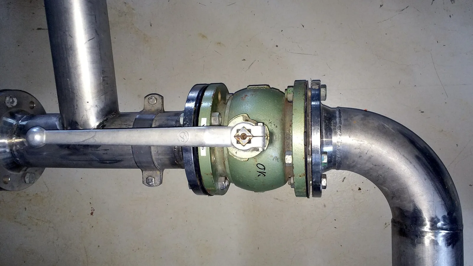
Table of Contents
An undersized actuator on a ball valve is not a slow failure — it is a valve that stops in mid-travel, a plant that trips on a stuck shutoff, and a site visit to swap hardware that was chosen from the wrong torque column. Ball valve torque is not a single catalog number: it climbs with valve size, pressure class and seat material, and the breakaway torque you need at the start of the stroke is almost always higher than the torque needed to keep the ball moving. Get the sizing method right and a rack and pinion actuator rated for the job opens and closes a 6-inch ball valve in under a second for years; get it wrong and the same actuator stalls at the worst possible moment.
This guide walks through the torque components that make up a ball valve's requirement, the practical difference between floating ball and trunnion-mounted ball designs, indicative torque ranges by size and pressure class, the safety factor margin that separates a reliable package from a marginal one, and the complete checklist to use when you spec a PNEUMACTUATOR actuated ball valve package with a distributor or integrator.
Keep reading for more!
The Snapshot
- Ball valve torque has three phases — breakaway (static), running and reseating — and breakaway is the highest of the three, which is why actuator sizing starts from the valve manufacturer's breakaway torque figure.
- Soft-seated floating ball valves from DN25 to DN300 (1" to 12") commonly show breakaway torques from roughly 8 N·m at Class 150 to 2,000 N·m or more at Class 300, depending on seat material, ball finish and differential pressure — the ranges in this guide are indicative, not a substitute for the valve maker's torque sheet.
- A safety margin of 25-50% over breakaway torque is a common industry starting point; spring return actuators should be checked at the spring end of the stroke, where output torque is at its lowest.
- Trunnion-mounted ball valves manage seat loading independently, so their torque per size is often lower at high pressure classes, but large trunnion valves are typically driven by scotch yoke actuators rather than rack and pinion units.
- Specify the whole package up front — ISO 5211 mounting, NAMUR solenoid, limit switch box, air filter regulator and manual override — so the actuator, valve and accessories arrive as one tested assembly.
Why Ball Valves Need Quarter-Turn Actuation
A ball valve shuts off by rotating a spherical plug 90 degrees — a quarter turn from fully open to fully closed. That geometry makes it one of the most common quarter-turn valves in process and utility service: full bore when open, a tight seal when closed, and a cycle that a pneumatic actuator executes naturally because the actuator's own 90-degree output rotation maps directly onto the valve stem. No linear-to-rotary conversion is needed, which is why rack and pinion and scotch yoke actuators dominate ball valve automation.
Pneumatic actuation earns its place on ball valves for three practical reasons. First, speed: a pneumatic rack and pinion actuator cycles a small ball valve in well under a second, and most sizes in a few seconds, which matters for emergency shutdown and tank blanketing service. Second, fail-safe behavior: a spring return actuator closes or opens the valve on air loss without any electrical supply, which is why gas skids and burner trains specify fail-closed ball valves as standard. Third, hazardous area suitability: pneumatic power has no motor, no arcing and no heat-generating windings, which simplifies ATEX-rated installations compared with electric actuators — a comparison covered in detail in our pneumatic vs electric actuator guide.
The engineering question is not whether to automate a ball valve — it is how to size the actuator so it can actually turn the ball under the worst operating conditions the valve will see. That starts with understanding where ball valve torque comes from.
What Makes Up Ball Valve Torque
Every ball valve has a torque requirement that changes through the stroke. Suppliers quote torque in three phases, and each plays a different role in sizing:
1. Breakaway (static) torque
The torque required to start the ball moving from a closed position against the seats. This is almost always the highest value in the set, because the ball is pressed into the downstream seat by line pressure and has been sitting there — static friction, seat deformation and any media film all add up. Breakaway torque is the number that sizes the actuator.
2. Running torque
The torque needed to keep the ball rotating once it is moving. It is typically 20-40% lower than breakaway on soft-seated valves once the seat-to-ball interface is sliding, though the exact ratio depends on the seat material and surface finish.
3. Reseating torque
The torque measured as the ball returns into the seat at the end of the stroke. It can exceed running torque and, on some designs, approach breakaway levels — a detail that matters when a spring return actuator must push the ball back into the seat using only its spring output.
Four factors drive the absolute values. Seat material is the largest: PTFE-based soft seats give the lowest friction, while PEEK, reinforced PTFE and metal seats add substantially more. Differential pressure across the ball increases the seat load on floating ball designs. Stem packing friction — O-rings, gland packing and any live-loading — adds a fixed contribution. And media effects, from viscosity to debris buildup on the ball surface, can multiply breakaway torque over time. This is why responsible suppliers publish torque values per valve model, and why the sizing workflow in this guide starts with the valve manufacturer's torque sheet rather than a generic table.
Floating Ball vs Trunnion-Mounted Ball
Ball valve construction splits into two families, and the split changes both the torque number and the actuator type. A floating ball valve lets the ball float freely between the seats; line pressure pushes the ball against the downstream seat, which creates the seal but also means seat load — and therefore torque — rises with pressure. A trunnion-mounted ball valve holds the ball on a fixed shaft (trunnion) at the bottom, so line pressure does not drive the ball into the seats; the seats are loaded by springs or by the seat design itself, which keeps torque more stable across pressure classes.
| Factor | Floating ball | Trunnion-mounted ball |
|---|---|---|
| Ball support | Free between seats | Fixed shaft (trunnion) top and bottom |
| Seal mechanism | Line pressure pushes ball into downstream seat | Seat loading controlled by springs / design |
| Torque vs pressure | Torque rises with pressure class | Torque relatively stable across pressure classes |
| Typical range | DN15-DN300, Class 150-600 | DN50 and up, Class 300 and above; large bore sizes |
| Common actuator | Rack and pinion | Scotch yoke (large sizes / high class) |
| Typical duty | Water, air, general process, on-off | Oil & gas, high pressure, pipeline, ESD |
The sizing consequence: for a floating ball valve you must size against the worst-case differential pressure the seat will see; for a trunnion valve the manufacturer's torque sheet is more predictive across operating points, but the absolute torque at large sizes is still substantial — a 12-inch trunnion ball at Class 600 can require several thousand N·m, which pushes the actuator choice toward scotch yoke. The torque profile of the two actuator families is explained in our rack and pinion vs scotch yoke comparison.
Ball Valve Torque by Size and Pressure Class
The table below gives indicative breakaway torque ranges for soft-seated (PTFE-based) floating ball valves in clean water or air service — the most common spec in general industrial automation. Values are industry-common starting points, not guarantees: the actual figure depends on the specific valve design, seat compound, ball finish, differential pressure and media, so treat this table as a first-pass estimate and confirm against the valve manufacturer's published torque sheet before committing to an actuator size.
| Nominal size | Class 150 / PN16 floating ball, soft seat (N·m) | Class 300 / PN40 floating ball, soft seat (N·m) | Typical rack & pinion actuator output class (at 5.5-8 bar) |
|---|---|---|---|
| DN25 (1") | 8-15 | 12-25 | ~30-60 N·m |
| DN40 (1.5") | 15-30 | 20-45 | ~60-100 N·m |
| DN50 (2") | 20-45 | 30-70 | ~100-160 N·m |
| DN80 (3") | 40-85 | 60-130 | ~160-300 N·m |
| DN100 (4") | 70-140 | 100-220 | ~300-500 N·m |
| DN150 (6") | 150-320 | 220-480 | ~500-900 N·m |
| DN200 (8") | 280-600 | 400-900 | ~900-1,600 N·m |
| DN250 (10") | 450-1,000 | 650-1,400 | ~1,600-2,800 N·m |
| DN300 (12") | 700-1,500 | 1,000-2,000+ | ~2,800-4,000 N·m (or scotch yoke) |
Adjusting the base values
Three adjustments cover most real-world deviations. Metal seats (or hard-faced seats) commonly push torque to roughly 1.5-2.5 times the soft-seat figure depending on materials and finish. A high differential pressure across the valve — for example a pump discharge holding pressure against a closed ball — adds seat load and can raise breakaway torque by 30-60% on floating ball designs. And viscous or dirty media, or a valve that sits closed for months, increases breakaway torque beyond the clean-service figure; the safety factor discussion below exists precisely to absorb this uncertainty.
Safety Factors and Why They Matter
Actuator sizing never uses raw breakaway torque. The industry norm is to multiply the valve's worst-case breakaway torque by a safety factor so the actuator delivers a comfortable margin over the requirement. A 25-50% margin (factor 1.25-1.5) is a common practice for general on-off ball valve duty, and many integrators treat 1.3-1.5 as their standard for spring return service because the spring end of the stroke delivers the lowest output torque. For critical or dirty service — ESD valves, media with buildup potential, valves that sit closed for long periods — a factor of 1.5 or higher is frequently specified, and some operators use 2.0 for applications where a stuck valve is unacceptable.
What the factor absorbs:
- Seat aging and swelling: PTFE-based seats can stiffen or swell with temperature and age, raising breakaway torque over the valve's life.
- Media effects: buildup, scale or crystallization on the ball surface adds friction that a new, clean valve does not show.
- Supply pressure variation: an actuator rated at 5.5-8 bar loses output roughly in proportion if shop air drops to 4 bar on a hot day.
- Spring return decay: spring torque falls as the spring extends; the torque available at the end of the stroke is the number to compare against the valve requirement.
The margin is cheap insurance: the next actuator frame size up typically adds modest cost against the alternative of a valve that fails to close during a plant upset.
Matching Actuator Output to Valve Torque
Actuator catalogs rate output torque at a reference supply pressure — commonly 5.5 bar or 8 bar (80-120 psi). The actual available torque scales with the actual supply pressure, so the comparison to make is: actuator output at your site's minimum supply pressure, at the end of stroke for spring return units, versus the valve requirement multiplied by your safety factor. If the plant air is regulated at 6 bar but the compressor setpoint droops to 5.2 bar under load, size against 5.2 bar, not the catalog figure.
Two actuator families cover ball valve duty. Rack and pinion actuators produce a roughly constant torque through the 90-degree stroke, which suits floating ball valves whose torque peak sits at breakaway. Scotch yoke actuators produce a torque curve that rises toward the closed position, which matches the torque profile of large ball valves and trunnion designs where the seat load peaks at closure — the reason scotch yoke units dominate the large-bore, high-class segment. The choice also interacts with fail-safe logic: a double acting actuator must hold the valve against pressure in both directions using air on both sides, while a spring return actuator uses spring force to reach the fail position, so its output requirement is calculated differently. Our double acting vs spring return guide walks through that logic in detail.
Mounting is the second half of the match. ISO 5211 defines the flange pattern, pilot bore and height that connect actuator to valve, and the interface must be confirmed for both torque class and physical size — a correctly sized actuator that does not bolt onto the valve flange is a common field surprise. The ISO 5211 mounting standard explained covers F10/F12/F14 patterns and how the coupling transmits torque to the stem.
Ball Valve Actuator Sizing: Step by Step
This is the workflow PNEUMACTUATOR engineers use when a distributor sends a valve model and a set of operating conditions:
1. Collect the valve data
Valve size, pressure class, seat material, trim, stem dimensions and the manufacturer's published breakaway torque — ideally for the actual model, at the actual differential pressure. If the vendor only gives a single torque figure, ask whether it is breakaway at rated class or at working conditions.
2. Confirm the operating envelope
Media, temperature, max differential pressure, cycle frequency, and the fail-safe requirement (fail closed / fail open / stay put). Temperature matters twice: it changes seat torque and it derates actuator seals.
3. Apply the safety factor
Required torque = worst-case breakaway torque × safety factor (start at 1.25-1.5; go higher for spring return, dirty media or critical duty).
4. Check the spring end for spring return units
Compare the actuator's end-of-stroke spring torque against the required torque at the fail position — this is the constraint that drives most single-acting sizes up one frame.
5. Select the actuator frame
Pick the rack and pinion or scotch yoke size whose output at the site's minimum supply pressure meets the required torque with margin. Double acting output and spring return output are read from different columns of the same catalog.
6. Verify the interface
Confirm ISO 5211 flange, pilot bore and coupling dimensions match the valve top flange, and that the drive insert fits the stem.
7. Spec the accessories
Solenoid valve, limit switch box, air filter regulator, manual override and any positioner — each one changes the package envelope, wiring and air consumption.
8. Validate with the supplier
Send the valve data sheet and conditions to the actuator manufacturer and let their engineers confirm the size. A supplier that pushes back with questions about differential pressure is doing the job properly.
The Complete Actuated Ball Valve Package
A "PNEUMACTUATOR actuated ball valve" is not one component — it is a valve, an actuator and a supporting set of accessories that must be specified as a system. The checklist below is the one to work through when requesting a quote, so the delivered package arrives complete and ready to install.
- Ball valve: size, class, end connections (flanged / threaded / welded), full bore vs reduced bore, seat material (PTFE / RPTFE / PEEK / metal) and the torque sheet.
- Actuator: double acting or spring return, fail position (FC / FO), output torque at the site supply pressure, ISO 5211 mounting flange, and enclosure/ATEX rating if required.
- Solenoid valve: NAMUR-mounted, 3/2 or 5/2 way, coil voltage (24 VDC / 110 VAC / 220 VAC), power consumption and hazardous-area rating.
- Limit switch box: mechanical or proximity switches, contact ratings, number of SPDT outputs, indicator dome visibility, and ATEX option for hazardous zones.
- Air filter regulator (FRL): filtration grade (5 µm is a common baseline), pressure range covering the actuator's rated supply, and drain type for the environment.
- Manual override: handwheel or manual override device for commissioning and power-down operation where the process requires it.
- Mounting kit: ISO 5211 bracket, coupling and fasteners sized for the valve stem — confirm the stem double-flat or keyway dimensions.
- Positioner (modulating service only): electro-pneumatic or digital positioner with the control signal (4-20 mA is the common baseline) if the valve throttles rather than just opens and closes.
- Documentation: torque calculation sheet, test certificate, material certificates and the actuator's performance data at the quoted supply pressure.
Accessory selection in more depth — NAMUR solenoids, limit switch boxes, positioners and manual overrides — is covered in our actuator accessories guide.
Common Sizing Mistakes
1. Sizing from running torque instead of breakaway
Running torque is 20-40% lower than breakaway on many soft-seated valves. An actuator sized on running torque stalls at the start of every stroke — the exact failure mode that looks like a mechanical jam but is actually a sizing error.
2. Ignoring the spring end of the stroke
A spring return actuator's output falls as the spring extends. Comparing the catalog "spring torque" at the compressed end against the valve requirement leaves the valve without enough force to finish closing.
3. Using the wrong supply pressure
Catalog torque is quoted at a reference pressure. If site air is 4 bar and the catalog says 8 bar, the available output is roughly half — with the safety factor consumed before the valve even moves.
4. Forgetting seat material
Switching a package from PTFE to metal seats without recalculating torque is a classic upgrade failure; the same valve size can need 1.5-2.5 times the actuator torque.
5. Treating the generic table as gospel
Every table in this guide is a starting point. Two identical-looking 4-inch Class 150 ball valves from different manufacturers can differ in breakaway torque by 30% or more depending on seat design and ball finish — the manufacturer's torque sheet is the only number to size against.
6. Overlooking the ISO 5211 interface
A torque-matched actuator with the wrong flange pattern, pilot bore or coupling will not mount. Confirm the interface in the same email as the torque data, not after delivery.
The Bottom Line
Ball valve actuator sizing is a four-number problem: the valve's breakaway torque at worst-case differential pressure, the safety factor you apply to it (1.25-1.5 is a common starting range), the actuator's output at your minimum supply pressure, and — for spring return units — the output available at the end of the spring stroke. Confirm the ISO 5211 interface, spec the accessories as a package, and the result is an actuated ball valve that cycles reliably for years. Get any one of those numbers from a generic table instead of the valve manufacturer's torque sheet, and you are gambling on hardware that either stalls in the middle of a stroke or carries a frame size you did not need.
Send us your valve model, size, pressure class and operating conditions — our engineers run the torque calculation and confirm the actuator size for you, free of charge.
Next Step
Ready to Spec Your Valve Actuator Package?
Send us your valve type, torque requirement and air supply — our engineers respond within 24 hours with sizing and pricing.
Written by
Ray ChanActuator engineer & technical writer. Ray helps global importers and integrators source factory-direct pneumatic actuators and valve automation packages.